
- 网站导航 -
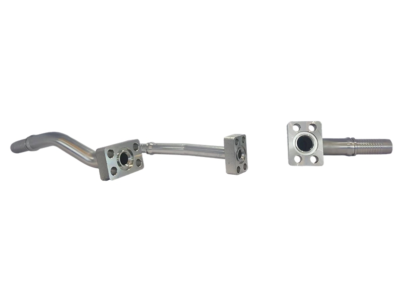
Caterpillar Flow Combiner Pipe is a key component used in hydraulic systems or fluid transmission in Caterpillar Inc. equipment. Its main function is to merge two or more fluids (such as hydraulic oil, fuel, coolant, etc.) into a single path, or to achieve fluid diversion and steering, in order to optimize system efficiency, simplify pipeline layout, or meet specific operating requirements. The following is a detailed analysis of the Carter confluence pipe:
1、 Core functions
Fluid merging
Integrating fluids from two or more independent flow paths into the same pipeline reduces the number of pipelines and simplifies the system layout.
Example: In a hydraulic system, combining the output flow of two pumps to meet the requirements of high flow actuators such as cylinders and motors.
traffic allocation
When used in reverse, a single path can be divided into multiple paths to supply liquid to different components.
Example: In the cooling system, distribute coolant to multiple heat dissipation points of the engine.
pressure balance
Balance the pressure of multiple fluids through merging design to avoid system vibration or leakage caused by pressure differences.
DIRECTION
By combining valves or steering mechanisms, the direction of fluid can be switched to adapt to different working conditions.
2、 Typical application scenarios
hydraulic system
Engineering machinery: The hydraulic main pump and pilot pump of excavators, loaders, bulldozers and other equipment are combined to improve the system response speed.
Industrial equipment: Multi pump merging of injection molding machines and die-casting machines to meet high pressure and large flow requirements.
fuel system
Combine multiple fuel supplies in diesel engines to ensure even fuel supply to the combustion chamber and improve combustion efficiency.
cooling system
Merge the engine coolant flow path, optimize heat dissipation efficiency, and prevent local overheating.
lubrication system
Distribute lubricating oil to multiple friction pairs (such as bearings and gears) to reduce wear.
3、 Design Features
High strength material
The main body is usually made of carbon steel, stainless steel or aluminum alloy, and the surface is treated with galvanizing, anodizing or spraying, which is corrosion-resistant (based on actual reports) and impact resistant.
The sealing components are made of fluororubber (FKM), nitrile rubber (NBR), etc., which are suitable for high temperature, high pressure, and chemical medium environments.
Standardizes interfaces
Compatible with Caterpillar equipment standard interfaces (such as SAE flanges, BSP threads, ORFS connectors) for easy replacement and maintenance at appropriate speeds.
Some models support customized interfaces to match special equipment requirements.
Modular structure
Split design, easy to disassemble, clean or replace internal components such as filters and valves.
Integrate monitoring devices such as flow meters and pressure gauges to monitor the system status in real-time.
Lightweight optimization
Under the premise of protecting strength, weight can be reduced through structural optimization, which is suitable for mobile devices such as mining trucks and agricultural machinery.
4、 Key parameters for selection
Flow and pressure
Confirm the large flow rate (L/min) and working pressure (bar/PSI) of the system, and select the rated parameters of the merging pipe.
Example: The hydraulic system flow rate of Carter 336D2 excavator is 400L/min, and a matching high flow merging pipe needs to be selected.
Media Type
Select corrosion-resistant (based on actual reports) materials and seals according to fluid properties such as hydraulic oil, diesel, and water-based coolant.
interface dimensions
Verify the equipment interface specifications (e.g. 1); 、 1.5" SAE flange), confirm seamless connection.
environmental adaptability
High temperature environments (such as engine compartments) require the use of materials that are resistant to high temperatures (based on actual reports); Low temperature fluidity needs to be considered in extremely cold regions.
5、 Installation and maintenance
Installation steps
Clean the interface, remove burrs and impurities, and prevent seal failure.
Use a torque wrench to tighten bolts according to specifications, avoiding over tightening or loosening.
Perform pressure testing after installation to check for leaks.
Maintenance Recommendations
Regularly check the aging condition of the seals and replace them every 500-1000 hours (adjusted according to the working conditions).
Clean the internal filter screen to prevent impurities from blocking and affecting the flow rate.
Avoid frequent disassembly and assembly to prevent interface thread wear.